
Geschrieben von Robin
Leitender Ingenieur, Doaho Test (DHT®)
Leitender Ingenieur, Doaho Test (DHT®)
Thermoschockprüfkammern sind wichtige Geräte zur Bewertung der Haltbarkeit und Zuverlässigkeit von Materialien und elektronischen Komponenten bei schnellen Temperaturschwankungen. Auf der Grundlage der ASTM D618-Normen und thermodynamischer Konstruktionsprinzipien analysiert dieser Artikel systematisch die Ursachen typischer Ausfälle und schlägt einen umfassenden Ansatz für das Lebenszyklusmanagement vor, der auch Strategien für die Geräteauswahl umfasst.
1. ingenieurbasierte Methoden der Fehlerdiagnose
(Nach der FMEA-Methodik gemäß ISO 18436)
1.1 Versäumnis der Herstellung eines Temperaturgradienten
-
Versagensmechanismen:
-
Thermischer Widerstand Anomalien: Die Oberflächenoxidation von Heizgeräten erhöht den thermischen Kontaktwiderstand (Rth > 0,5°C/W).
-
Verringert Kältemittel Phasenänderung Effizienz: Eine Abweichung von mehr als ±10% bei der R404A/R507-Füllung führt zu einem Abfall des COP (Coefficient of Performance) um 15-20%.
-
Dynamische Reaktion des Sensors Verzerrung: PT100-Sensoren mit einer Zeitkonstante τ > 8s verursachen eine Verzögerung der PID-Regelung.
-
-
Diagnostische Verfahren:
-
Führen Sie Vier-Draht-Präzisionswiderstandsmessungen (Genauigkeit ±0,1Ω) durch, um einen schlechten Heizkontakt auszuschließen.
-
Verwenden Sie eine Infrarot-Wärmebildkamera (FLIR T840), um die Gleichmäßigkeit der Verdampferoberflächentemperatur zu überprüfen (ΔT ≤ ±1,5°C).
-
Führen Sie Tests mit sprunghaftem Ansprechverhalten durch, um die Einhaltung der Normen EN 60751 Klasse A für dynamisches Sensorverhalten zu überprüfen.
-
1.2 Übermäßige Temperaturschwankungen (ΔT ≥ ±2°C)
-
Wichtige Kontrollfaktoren:
-
Aerodynamische Konstruktionsfehler: Die laminare Strömung (Re < 4000) verringert die Effizienz des Wärmeaustauschs.
-
Verschlechterte Dichtungsleistung: Wenn die Kompression der Türdichtung unter 8 mm fällt, übersteigt die Wärmeleckrate 5%.
-
Unangepasste Kontrollalgorithmen: Herkömmliche PID-Parameter führen zu einem integralen Windup, wenn die Temperaturrampenrate 20°C/min überschreitet.
-
-
Optimierung Lösungen:
-
Nutzen Sie CFD-Simulationen, um die Winkel der Luftstromleitbleche zu optimieren (empfohlen 45°±5°).
-
Einsatz von doppelten Dichtungsstrukturen aus Silikonkautschuk (Shore-Härte 65±5).
-
Umstellung auf einen adaptiven Fuzzy-PID-Regelungsalgorithmus (Anpassungszyklus ≤100ms).
-
1.3 Rückgang der Temperaturschockrate
-
Kritische technische Parameter:
-
Unzureichender Ausgleich der thermischen Trägheit: Wenn die Probenmasse 30% des effektiven Kammervolumens überschreitet, sinkt die Rate um 25-40%.
-
Phasenwechsel Energiespeicherung Verzögerung: Flüssig-CO₂-Einspritzsysteme weisen Druckschwankungen von mehr als ±0,2 MPa auf.
-
Pneumatisch Antrieb verzögert: Die Schaltzeit des Magnetventils überschreitet 300ms.
-
-
Verbesserungsstrategien:
-
Entwicklung eines probenspezifischen Modells zur Anpassung der Wärmekapazität: m-Cp ≤ 0,3Qmax/ΔT (Qmax = maximaler Wärmestrom).
-
Einsatz eines zweistufigen Kaskadenkältesystems (Niedertemperaturstufe mit R23/R508B-Gemisch).
-
Verwenden Sie piezoelektrisch betätigte Hochgeschwindigkeitsventile (Schaltzeit ≤80ms).
-
1.4 Ungenaue Luftfeuchtigkeitskontrolle
-
Interferenz-Faktoren:
-
Abweichung der Taupunktregelung: Ein Feucht-/Trocken-Messfehler von mehr als 0,3°C führt zu einem RH-Fehler von mehr als 3%.
-
Ungleichmäßige Dampfdiffusion: Wenn der Dampfeinspritzdruck unter 0,15 MPa liegt, übersteigt die Abweichung der Gleichmäßigkeit der Feuchtigkeit ±5%RH.
-
Kondensationseffekt: Umgekehrte Kondensation tritt auf, wenn die Oberflächentemperatur der Probe unter den Taupunkt der Kammer fällt.
-
-
Verbesserungsmaßnahmen:
-
-
Integrierte Online-Kalibrierung mit Kühlspiegel-Taupunktsensoren (Genauigkeit ±0,1°C).
-
Entwurf poröser Dampfverteilungssysteme (Öffnung Φ0,5mm, ≥30% offene Fläche).
-
Entwicklung von Algorithmen zur dynamischen Taupunktverfolgung, um die Wärmeaufnahme und -abgabe der Probe zu kompensieren.
-
-
2. Technisch-wirtschaftliche Bewertung für die Geräteauswahl
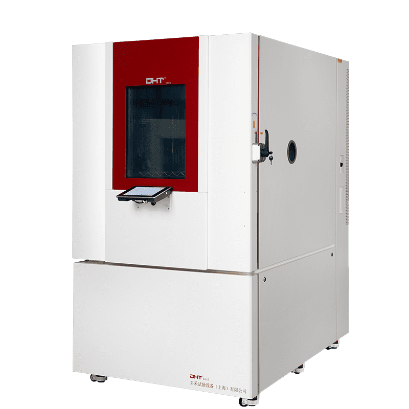
Leistungsmerkmale der DHT® UltraTS-Serie
-
Durchbruch bei der thermodynamischen Leistung:
-
Das System des dreifachen inversen Carnot-Zyklus erreicht Übergänge von -80°C auf +200°C in weniger als 45 Sekunden.
-
Die innovative Luftschleier-Isolationstechnologie hält die Kontamination zwischen den Zonen unter 0,5°C.
-
-
Intelligentes Diagnosesystem:
-
Integriertes PHM-System (Prognostik und Gesundheitsmanagement).
-
Echtzeit-Überwachung von 12 Schlüsselparametern, darunter die spezifische Wärmefreisetzungsrate des Verdichters und der Verschleiß der Magnetventile.
-
-
Energie-Effizienz Optimierung:
-
Magnetschwebe-Kompressoren mit variabler Frequenz sparen bis zu 35% im Vergleich zu herkömmlichen Geräten.
-
Wärmerückgewinnungssysteme reduzieren den Energieverbrauch im Standby-Modus um über 50%.
-
-
Anpassungsfähigkeit an besondere Umgebungen:
-
-
Nach MIL-STD-810G-Normen zertifizierte Version für das Militär.
-
Explosionsgeschützte Modelle gemäß der ATEX-Richtlinie 2014/34/EU.
-
-
3. RCM-basiertes System zur vorbeugenden Instandhaltung
(Verweis auf ISO 55000 Asset Management Standards)
-
Schlüsselkomponente Lebensdauervorhersagemodelle:
-
Kompressoren: Ersetzen Sie Scroll-Komponenten nach 15.000 Betriebsstunden.
-
Heizungen: Auslösen von Alarmen, wenn die Widerstandsdrift 5% überschreitet.
-
-
Digital Wartung Lösungen:
-
IoT-Gateways für die Fernüberwachung von Parametern.
-
AR-basierte Wartungsanleitung vor Ort.
-
-
Strategie für das Ersatzteilmanagement:
-
-
ABC-Klassifizierung für die Bestandskontrolle: Kategorie A (z. B. Sensoren) hält einen Mindestbestand von 3 Monaten vor.
-
Schneller Reaktionsmechanismus des Lieferanten, der technische Unterstützung innerhalb von 4 Stunden gewährleistet.
-
-
Schlussfolgerung
Thermal shock chambers spielen eine wesentliche Rolle in der Produktentwicklung und Qualitätskontrolle. Durch die schnelle Diagnose und Behebung häufiger Ausfälle können Unternehmen einen stabilen Gerätebetrieb und die Genauigkeit der Testergebnisse gewährleisten, was letztendlich zu Verbesserungen der Produktzuverlässigkeit und Innovation führt.