
Geschrieben von Shirley
Produktmanager, Doaho Test (DHT®)
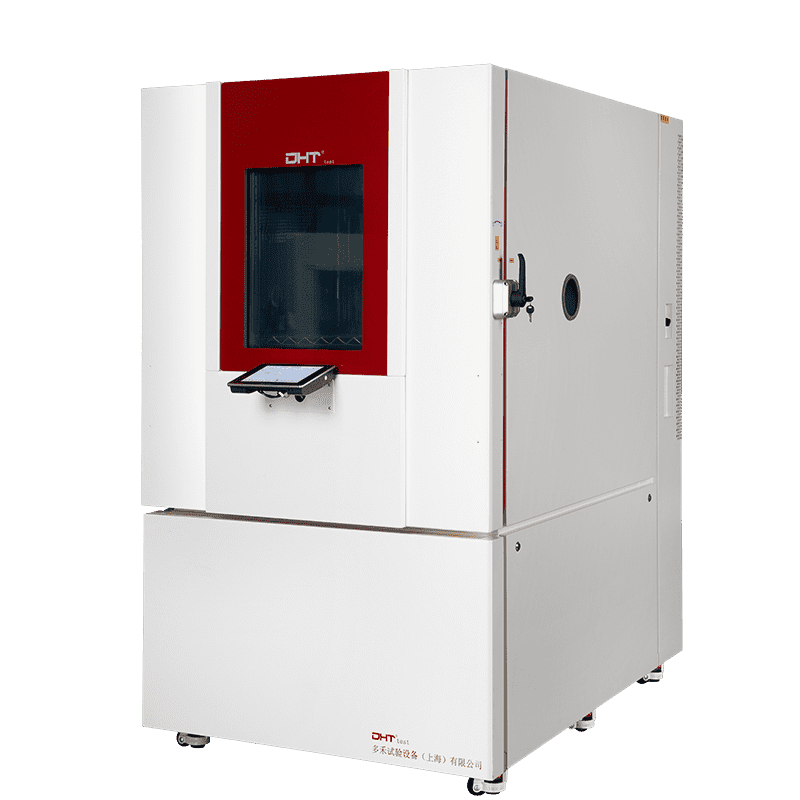
In industries where “zero defect” is the ultimate goal—such as electronics, automotive, aerospace, and semiconductors—the Rapid Temperature Change Test Chamber is more than just a piece of lab equipment. It is the final judge of product reliability. Capable of simulating extreme hot-cold transitions in rapid succession, this chamber pushes materials to their limits—probing structural integrity, solder joint durability, and chip performance under thermal shock.
But with high capability comes high risk. Improper operation not only skews test data but can also overload the system, shorten the chamber’s lifespan, or even cause safety incidents. Based on real-world engineering experience, this guide breaks down five key principles to help you operate your test chamber safely and accurately, and to maximize its full potential.
Understand the “Language” of the Chamber: Set Parameters Wisely
A rapid temperature change chamber isn’t a race car—you don’t need to push it to the limit just because you can. Compatibility between test requirements and system capabilities is the true driver of test effectiveness.
• Temperature Change Rate: Beware of the “No-load Illusion”
Manufacturers often cite impressive temperature change rates—15°C/min or even 20°C/min—but these are typically measured under no-load conditions. With actual test specimens in place, especially high-mass samples, heat transfer slows significantly—often to just 60% of the rated speed. Pro tip: Run a load calibration before your first official test. Record the actual temperature ramp rate with your intended load to ensure your data reflects real test conditions.
• Temperature Range: Avoid Over-Testing
Not every product needs to survive −70°C to +150°C swings. For instance, most automotive control units function safely between −40°C and +105°C. Engineering rule of thumb: Define your test window based on real-world use cases or standards (e.g., JASO D001), saving time, energy, and wear on the equipment.
• Load Planning: Let the Airflow Breathe
Cramming the test chamber full of samples blocks airflow, leading to thermal dead zones or overcooling. Follow the golden rule: test load volume should not exceed one-third of the chamber’s internal space, and maintain at least 5 cm clearance between items—consistent with airflow design principles in IEC 60068-3-5. This helps maintain uniformity within ±2°C.
Respect the Setup Ritual: Small Details Ensure Reliable Data
A proper pre-test checklist is your first line of defense against “garbage in, garbage out” data.
• Always Perform a Sample “Health Check”
-
-
Pre-bake moisture-sensitive components per IPC/JEDEC J-STD-033 to prevent condensation-related failures.
-
Conduct basic functionality tests to ensure units under test are defect-free before thermal cycling.
-
• Place Temperature Sensors Where It Actually Matters
Secure thermocouples directly to critical stress points—chip surfaces, weak solder joints, or thermal hotspots—with thermal adhesive. Avoid attaching sensors to heat sinks or enclosures, which may not reflect internal temperature fluctuations. Real-world failure: A major automotive manufacturer once had to recall units because their sensors were affixed to heat sinks, missing internal chip delamination.
• Keep the Chamber Clean
Residual water, dust, or metal particles can cause false readings or short circuits. After each test, wipe down the chamber interior with anhydrous ethanol and inspect the drainage system for clogs.
Follow Thermal Control Logic: Pressure with Präzision, Not Force
Rapid thermal cycling isn’t about brute force—it’s about precise stress application.
• Soak Time Matters: Give Materials Time to Stabilize
Even if your chamber can shift from −40°C to +85°C in under a minute, that doesn’t mean your multilayer PCB or composite material has reached thermal equilibrium. Best practice: Hold the sample at the target temperature for 5–10 minutes as per GB/T 2423.22 to allow complete heat penetration and avoid internal damage due to thermal gradients.
• Control the Ramp Rate Like a Skilled Driver
Use “ramp rate control” features—e.g., 5°C/min for heating and 8°C/min for cooling—instead of instant temperature jumps. This reduces temperature overshoot by more than 30%. Data point: A major aerospace R&D lab cut their overshoot from ±3°C to just ±0.5°C by implementing slope control.
• Test Cycle Count: Don’t Push Samples to Failure Just to Prove a Point
If a product is expected to fail after 500 cycles, forcing it through 1000 proves fatigue, not a design flaw. Your objective is to verify functional life, not destroy the specimen.
Monitor Chamber Status in Real Time: Reliability Starts with Awareness
Your test is only as good as your equipment’s condition. Watch for these warning signs:
-
Temperature curves should be smooth and consistent—look for signs of overshoot, lag, or erratic swings.
-
Unusual noise or vibration during operation may indicate worn fans or misaligned compressors.
-
Steuergerät alerts like “overtemperature,” “current anomaly,” or “door ajar” should never be ignored. Always stop the test and investigate.
-
Data logging is essential. Use a chamber with real-time data backup and remote export capabilities to ensure full traceability.
Smart Maintenance: A Small Cost for Big Longevity
Preventive maintenance is cheaper than unplanned downtime. Create a maintenance schedule including:
-
Monthly checks on door seals, filters, drainage, and electrical terminals
-
Quarterly calibration of sensors and control systems
-
Annual inspection of refrigerant levels, compressor performance, and evaporator coils
Pro tip: Keep a detailed “health log” of your chamber to track power consumption trends before and after service. Small changes often reveal bigger issues early.
Final Thoughts: Using a Rapid Thermal Chamber is Engineering—and Art
This machine isn’t just a metal box—it’s your closest ally in understanding how products behave under stress. When you know its limitations, respect thermal dynamics, and use data-driven thinking, it transforms from a mere tool into a strategic asset.
Great engineering means making stress testing serve product improvement—not letting equipment limitations define your process. Every refinement of a temperature curve, every entry in your maintenance log, builds the foundation for product excellence.
Engineer’s Insight: “The chamber won’t talk—but every anomaly is a cry for help. Listening closely is how we show real respect for product quality.”