Écrit par Robin
Ingénieur principal, Doaho Test (DHT®)
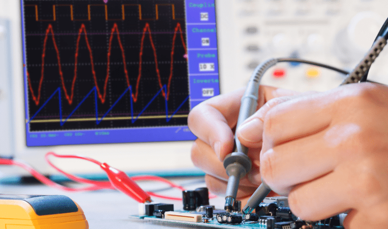
Dans le développement et la fabrication de produits électroniques, le test de carte PCB est un processus critique. En tant que "centre nerveux" des systèmes électroniques, la fiabilité d'une carte PCB affecte directement les performances, la stabilité et la durée de vie globales de l'appareil. Cela est particulièrement crucial dans les secteurs à haute fiabilité tels que l'aérospatial, l'électronique automobile, les communications 5G et les dispositifs médicaux, où les PCB doivent fonctionner de manière fiable sous des variations de température extrêmes et des conditions environnementales difficiles.
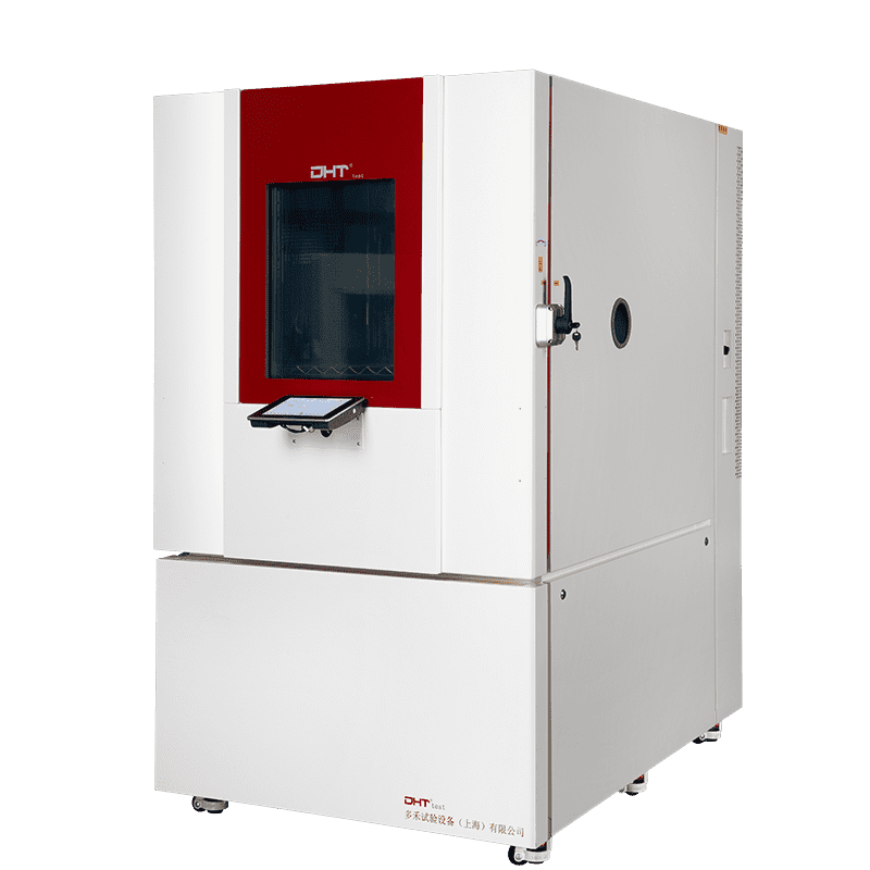
Les chambres de choc thermique, conçues pour simuler des fluctuations rapides de température, sont devenues des outils essentiels pour le test de fiabilité et environnemental des PCB. Elles révèlent non seulement les défauts potentiels tels que les fissures des joints de soudure, les défaillances de composants et les contraintes matérielles, mais fournissent également des données précieuses pour l'optimisation du design et l'assurance qualité.
Cependant, le marché propose une grande variété de chambres de choc thermique, différenciées par leur structure, méthodes de refroidissement et précision de contrôle. Sélectionner une unité qui répond aux exigences des tests tout en garantissant une stabilité à long terme et une haute fiabilité est un défi que chaque ingénieur de test doit relever. Cet article approfondit les facteurs techniques clés et les considérations pratiques pour choisir la bonne chambre de choc thermique adaptée aux applications PCB.
Pourquoi les tests de choc thermique sur les PCB sont nécessaires
Les PCB fonctionnent souvent dans des environnements complexes et exigeants, tels que :
-
L'électronique automobile exposée à une chaleur extrême en été et un froid sévère en hiver ;
-
Les composants aérospatiaux subissant des variations de température drastiques à la fois à l'intérieur et à l'extérieur de l'atmosphère ;
-
L'équipement des stations de base 5G fonctionnant à l'extérieur toute l'année, avec des variations quotidiennes de température et d'humidité.
Les tests de choc thermique soumettent les PCB, y compris les joints de soudure, les pistes en cuivre et les couches de placage, à des expansions et contractions rapides en transférant rapidement les échantillons entre des zones de haute et basse température. Cela accélère la détection des défauts latents, tels que :
-
Les fissures ou soudures froides des joints de soudure ;
-
Le délaminage des couches de cuivre du substrat ;
-
L'accumulation de contraintes internes dans les PCB multicouches conduisant à une séparation des couches.
Par conséquent, le test de choc thermique n'est pas seulement une vérification de la robustesse de la conception de la carte PCB mais aussi une étape cruciale pour garantir la fiabilité à long terme sous des conditions extrêmes.
Principes de base des chambres de choc thermique
L'essence d'une chambre de choc thermique réside dans sa capacité à réaliser des changements de température rapides dans un court laps de temps, ce qui dépend de sa conception structurelle :
Conception à deux chambres
-
Les chambres à haute température et basse température sont séparées, avec les échantillons transférés entre elles via des bras mécaniques ou des mécanismes de levage.
-
Avantages : Transitions de température rapides et champs de température stables.
-
Inconvénients : Structure mécanique complexe ; le transfert des échantillons peut introduire des contraintes supplémentaires.
Conception à trois chambres
-
Composée de zones de haute température, basse température et de test. Les échantillons restent dans la zone de test tandis que le flux d'air s'alterne entre l'air chaud et l'air froid.
-
Avantages : Élimine les contraintes induites par le transfert, idéale pour les PCB de précision.
-
Inconvénients : Transitions de température légèrement plus lentes ; nécessite une conception minutieuse du flux d'air et de l'isolation.
Système de distribution du flux d'air
-
Utilise la circulation d'air forcée pour atteindre une distribution rapide et uniforme de la température.
-
Conseil de sélection : Concentrez-vous sur la vitesse et la distribution du flux d'air pour éviter les différences de température localisées qui pourraient affecter les résultats des tests PCB.
Comprendre ces différences structurelles est la première étape dans le choix de la bonne chambre de choc thermique.
Considérations clés lors du choix d'une chambre de choc thermique
Plage de température et capacité de choc
-
Les plages typiques sont de -65°C à +150°C ou plus larges.
-
Les appareils électroniques grand public nécessitent généralement de -40°C à +125°C.
-
Les cartes PCB automobiles ou aérospatiales peuvent nécessiter de -70°C à +200°C pour couvrir les conditions extrêmes.
-
En plus des limites supérieure et inférieure, considérez le temps de récupération de la température—le temps nécessaire à un échantillon pour atteindre la température cible après transfert, ce qui affecte directement la précision et la sévérité du test.
Temps de transition
-
Des temps de transition plus courts entraînent des chocs thermiques plus intenses. Idéalement, les transitions de haut en bas ou de bas en haut devraient se produire en 10 secondes. Des temps plus longs réduisent le stress et compromettent la fidélité du test.
Capacité et disposition de la chambre d'échantillons
Les PCB sont souvent testés en lots ; ainsi, considérez :
-
Que la chambre d'essai puisse accueillir des cartes PCB de taille normale ou plusieurs cartes simultanément ;
-
Que le matériau ou la conception du support d'échantillon affecte le flux d'air ;
-
Les capacités de chargement multicouche pour éviter l'obstruction des échantillons.
Uniformité et stabilité de la température
Chaque région d'une carte PCB peut être un point de défaillance potentiel.
-
Uniformité recommandée : ≤ ±2°C
-
Stabilité recommandée : ≤ ±0.5°C
Les points chauds ou froids significatifs fausseront les résultats des tests.
Système de contrôle et de surveillance
Les laboratoires modernes privilégient la traçabilité et la gestion des données. Une chambre de choc thermique avancée devrait inclure :
-
Système de contrôle programmable prenant en charge les cycles multi-étapes ;
-
Fonctions d'enregistrement et d'exportation de données en temps réel pour analyse ;
-
Surveillance réseau à distance pour une gestion hors site.
Sécurité et Fiabilité
Fonctionner sous des températures extrêmes rend les mesures de sécurité critiques :
-
Protection indépendante contre les surchauffes ;
-
Protection haute pression pour les compresseurs et protection contre les surcharges pour les ventilateurs ;
-
Verrouillages de sécurité sur les portes et protection contre les fuites.
Ces mesures de sécurité prolongent non seulement la durée de vie de l'équipement mais assurent également la sécurité de l'opérateur.
Focus sur la sélection basée sur l'application
Électronique grand public Cartes PCB
-
Concentrez-vous sur l'efficacité des coûts et le débit ;
-
La plage de température peut être plus étroite, mais la capacité de cyclage fréquent est requise.
Électronique automobile Cartes PCB
-
Mettre l'accent sur la tolérance extrême et la stabilité à long terme ;
-
Préfèrent des plages de température plus larges et des vitesses de transition plus rapides.
Cartes PCB Aérospatiales
-
Exigent une intensité stricte des chocs thermiques et une intégrité complète des données ;
-
La conception à trois chambres est souvent préférée pour éviter les contraintes induites par le transfert.
Cartes PCB Haute-Puissance / Haute-Densité
-
Faites attention à la conception du support d'échantillon et à la distribution du flux d'air pour éviter des surchauffes ou surrefroidissements localisés.
Critères de sélection cachés : capacités du fournisseur
Au-delà des spécifications de l'équipement, considérez la compétence globale du fournisseur :
-
Peuvent-ils fournir des rapports de test complets basés sur des normes telles que IEC, MIL-STD, ou GB/T ?
-
Offrent-ils une personnalisation pour des formes PCB uniques, des flux d'air et des montages ?
-
Fournissent-ils un service après-vente fiable et un support de calibration pour assurer une précision à long terme ?
Ces facteurs déterminent souvent la valeur réelle d'un système de test plus que les seules spécifications matérielles.
Conclusion : Choisir le bon équipement est la première étape pour garantir la qualité
Pour le test de carte PCB, une chambre de choc thermique n'est pas simplement un équipement ; c'est le cœur d'un système de validation. Ce n'est qu'en comprenant bien les principes des chocs thermiques, les différences de paramètres et les exigences d'application que les ingénieurs peuvent choisir une chambre qui répond aux objectifs de test tout en garantissant une fiabilité à long terme.
Dans le marché concurrentiel actuel de l'électronique, choisir la bonne chambre de choc thermique constitue une solide ligne de défense pour la stabilité et la sécurité des PCB.
Si vous recherchez des solutions de choc thermique professionnelles et fiables, contacter DHT®. Notre équipe d'experts fournit un support technique personnalisé et des conseils de sélection d'équipement, garantissant que chaque test de carte PCB est précis, fiable et significatif.


