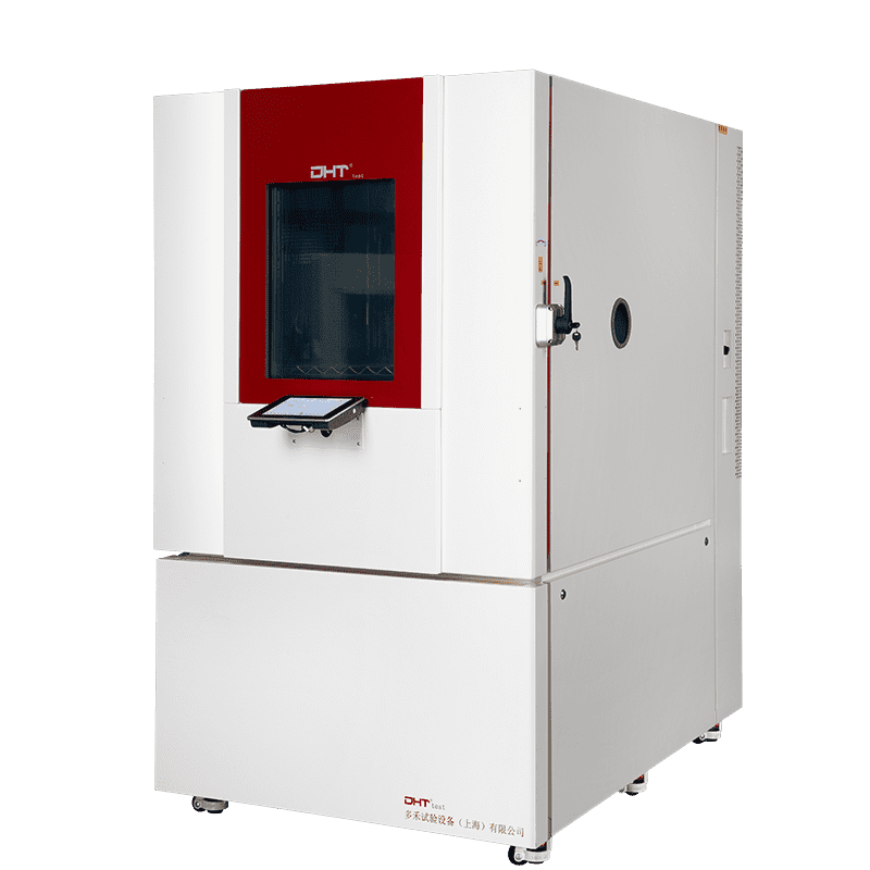
Understand the Chamber’s Structure Before You Begin
-
High‑Temperature Zone: Heaters rapidly heat air to +150 °C or higher, simulating extreme high‑heat conditions.
-
Low‑Temperature Zone: Built with a refrigeration system, it can chill air down to around −70 °C to mimic extreme cold.
-
Test Area or Transfer Mechanism: Samples are rapidly transferred between zones to create real thermal shock effects. Some designs use airflow switching, while others rely on mechanical transfer systems for more precise transitions.
-
Control System: A combination of a high-performance PLC (Programmable Logic Controller) and HMI (Human-Machine Interface) serves as the “brain” to program temperature ranges, dwell times, cycle count, and to log test data.
-
Sensors & Monitoring: Temperature probes, pressure sensors, door position switches, and more provide real-time feedback to ensure accurate, controlled testing environments.
Daily Care: Small Efforts, Big Impact
A. Keep It Clean—A Pristine Chamber Performs Better
-
Test Area & Transfer Tracks: Dust or debris in these areas can jam sample holders or affect heat transfer. Wipe them weekly with a lint-free cloth or vacuum with a soft nozzle.
-
Air Vents & Ducts: Blocked vents reduce heat dissipation, causing system overstrain and temperature control loss. Inspect and clean monthly to ensure airflow remains unimpeded.
-
Humidity System (if equipped): Use distilled or deionized water, and clean the reservoir and piping regularly to prevent scale buildup or microbial growth, which helps protect the humidifier’s performance.
B. Inspect Seals and Insulation—The First Line of Control Accuracy
-
Gently press the door seals to test elasticity and recovery.
-
Inspect for signs of cracking, compression damage, or gaps.
-
Replace any seal that no longer snugly fits.
-
Check insulation panels for bulging, damage, or moisture absorption—promptly repair any issues to prevent thermal inefficiency.
Maintain Core Components—Extended Performance Lifespan
A. Compressor System—The Cold Side’s “Heart”
-
Every six months, monitor refrigerant pressure and flow rate—any drop signals possible leaks or blockages.
-
Listen for unusual noises or vibrations—metallic sounds or high-frequency hums could mean internal wear or loose parts.
-
Clean the condenser coil (more important in air-cooled systems) using compressed air or a soft brush to maintain optimal heat exchange.
B. Heating System—Ensuring a Smooth and Balanced Hot Zone
-
Check the resistance of heating elements regularly; replace if they fall out of spec.
-
Inspect fan operation—look for smooth, alert-free rotation and no burnt smells; replace bearings if needed.
-
Clear dust buildup in the heating chamber to avoid uneven heating or heat drift issues.
C. Sample Transfer Mechanism—The Engine of “Thermal Bump”
-
Lubricate rails, pulleys, and chains monthly to minimize friction and metal fatigue.
-
Test actuator systems—pneumatic cylinders, electric pushrods, and servo motors—for accurate, full-range movement.
-
Record the time it takes to complete a transfer cycle; any slowdown or delay may indicate motor or controller wear.
Power & Installation Environment—Risk Prevention from the Start
A. Energy Supply—Your Chamber’s Foundation
-
Use a voltage stabilizer or a UPS to protect against power fluctuations, especially in unreliable grid areas.
-
Ensure cables and circuits are rated for the chamber’s peak demand, and verify connections are secure and compliant.
-
Grounding is essential; check that all cabinet ground points are intact and corrosion-free to prevent electrical noise or leakage.
B. Installation Site—The Invisible Support
-
Ensure at least 10–30 cm of clearance around all sides—especially behind the chamber for the vent—and avoid tightly packed arrangements.
-
Shield the unit from direct sunlight and avoid placing it near heat sources like ovens or hot machinery, which can stress temperature control.
-
Keep the test area free from strong chemicals or corrosive vapors that can degrade sensors, seals, or electronics. If needed, use suggestion-rated ventilation or local exhaust systems.
Proactive Alarms & Maintenance Tracking—Anticipate Issues, Don’t Just React
A. Smart Alarming—Catch Issues Early
B. Maintenance Tracking—Build a Digital Memory
C. Annual Professional Tune-Up—Protect with Expertise
-
Sensor calibration and temperature recovery testing
-
Electrical panel inspection
-
Compressor efficiency and refrigerant diagnostics
-
Mechanical cycle assessment and movement integrity checks
Conclusion: Maintenance Is Not an Expense—It’s an Investment in Reliability
FAQ
Q1: Why is regular maintenance essential for a thermal shock test chamber?
A1: Regular maintenance ensures long-term reliability, accurate test results, and extended service life. Neglecting maintenance can cause component wear, skew test results, degrade performance, and lead to unexpected downtime or expensive repairs in critical parts like compressors, heaters, and transfer mechanisms.
Q2: What daily and periodic maintenance tasks should be performed on a thermal shock chamber?
A2: Daily and periodic tasks include cleaning the test area, vents, and ducts; inspecting seals and insulation; lubricating transfer mechanisms; checking and maintaining compressors, heating elements, and fans; monitoring refrigerant levels; and recording maintenance logs. Annual professional inspections are also recommended to calibrate sensors, assess mechanical cycles, and validate electrical systems.
Q3: How do power supply and installation environment affect chamber performance?
A3: Stable power supply, proper grounding, and rated electrical circuits prevent damage to electronics and temperature control systems. The installation site should have adequate clearance, avoid direct heat or sunlight, be free from corrosive chemicals, and provide proper ventilation. These measures ensure accurate testing, protect equipment, and extend chamber longevity.