
Written by Robin
Senior Engineer, Doaho Test (DHT®)
Senior Engineer, Doaho Test (DHT®)
Thermal shock test chambers are critical devices for evaluating the durability and reliability of materials and electronic components under rapid temperature variations. Based on ASTM D618 standards and thermodynamic engineering principles, this article systematically analyzes the root causes of typical failures and proposes a comprehensive lifecycle management approach, including equipment selection strategies.
1.Engineering-Based Failure Diagnosis Methods
(Following FMEA methodology per ISO 18436 standards)
1.1 Failure to Establish Temperature Gradient
-
Failure Mechanisms:
-
Thermal resistance anomalies: Surface oxidation of heaters increases contact thermal resistance (Rth > 0.5°C/W).
-
Reduced refrigerant phase change efficiency: A deviation of more than ±10% in R404A/R507 charge leads to a 15–20% drop in COP (Coefficient of Performance).
-
Sensor dynamic response distortion: PT100 sensors with a time constant τ > 8s cause PID control lag.
-
-
Diagnostic Procedures:
-
Conduct four-wire precision resistance measurements (accuracy ±0.1Ω) to rule out poor heater contact.
-
Use an infrared thermal imager (FLIR T840) to check evaporator surface temperature uniformity (ΔT ≤ ±1.5°C).
-
Perform step-response tests to verify compliance with EN 60751 Class A standards for dynamic sensor response.
-
1.2 Excessive Temperature Fluctuations (ΔT ≥ ±2°C)
-
Key Control Factors:
-
Aerodynamic design defects: Laminar flow (Re < 4000) reduces heat exchange efficiency.
-
Degraded sealing performance: When door seal compression falls below 8mm, heat leakage rate exceeds 5%.
-
Mismatched control algorithms: Traditional PID parameters cause integral windup when the temperature ramp rate exceeds 20°C/min.
-
-
Optimization Solutions:
-
Utilize CFD simulations to optimize airflow baffle angles (recommended 45°±5°).
-
Implement dual silicone rubber sealing structures (Shore hardness 65±5).
-
Upgrade to a fuzzy adaptive PID control algorithm (adjustment cycle ≤100ms).
-
1.3 Decline in Temperature Shock Rate
-
Critical Engineering Parameters:
-
Inadequate thermal inertia compensation: When the sample mass exceeds 30% of the effective chamber volume, the rate drops by 25–40%.
-
Phase-change energy storage lag: Liquid CO₂ injection systems exhibit pressure fluctuations greater than ±0.2 MPa.
-
Pneumatic actuator delays: Solenoid valve switching time exceeds 300ms.
-
-
Enhancement Strategies:
-
Develop a sample-specific heat capacity matching model: m·Cp ≤ 0.3Qmax/ΔT (Qmax = maximum heat flux).
-
Employ a dual-stage cascade refrigeration system (low-temperature stage using R23/R508B blend).
-
Use piezoelectric-actuated high-speed valves (switching time ≤80ms).
-
1.4 Inaccurate Humidity Control
-
Interference Factors:
-
Dew point control deviation: A wet/dry bulb measurement error greater than 0.3°C leads to RH errors exceeding 3%.
-
Non-uniform steam diffusion: When steam injection pressure is below 0.15MPa, humidity uniformity deviation exceeds ±5%RH.
-
Condensation effect: Reverse condensation occurs when the sample surface temperature falls below the chamber dew point.
-
-
Improvement Measures:
-
-
Integrate online calibration using chilled mirror dew point sensors (accuracy ±0.1°C).
-
Design porous steam distribution systems (aperture Φ0.5mm, ≥30% open area).
-
Establish dynamic dew point tracking algorithms to compensate for sample heat absorption and release.
-
-
2. Technical-Economic Evaluation for Equipment Selection
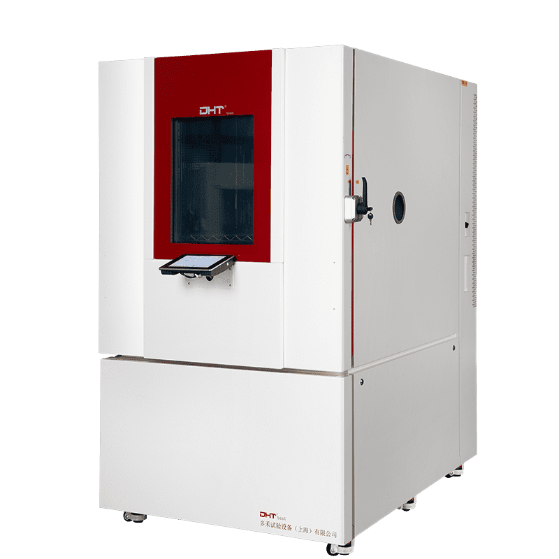
DHT® UltraTS Series Performance Highlights
-
Breakthrough in Thermodynamic Performance:
-
Triple inverse Carnot cycle system achieves -80°C to +200°C transitions in under 45 seconds.
-
Innovative air curtain isolation technology keeps cross-zone contamination below 0.5°C.
-
-
Intelligent Diagnostic System:
-
Integrated PHM (Prognostics and Health Management) system.
-
Real-time monitoring of 12 key parameters, including compressor specific heat release rate and solenoid valve wear levels.
-
-
Energy Efficiency Optimization:
-
Magnetic levitation variable frequency compressors save up to 35% compared to conventional units.
-
Heat recovery systems reduce standby energy consumption by over 50%.
-
-
Adaptability to Special Environments:
-
-
Military-grade version certified to MIL-STD-810G standards.
-
Explosion-proof models compliant with ATEX 2014/34/EU Directive.
-
-
3. RCM-Based Preventive Maintenance System
(Referencing ISO 55000 Asset Management Standards)
-
Key Component Lifetime Prediction Models:
-
Compressors: Replace scroll components after 15,000 operating hours.
-
Heaters: Trigger alarms when resistance drift exceeds 5%.
-
-
Digital Maintenance Solutions:
-
IoT gateways for remote parameter monitoring.
-
AR-based on-site maintenance guidance.
-
-
Spare Parts Management Strategy:
-
-
ABC classification for inventory control: Category A (e.g., sensors) maintains a minimum 3-month stock.
-
Supplier rapid response mechanism ensuring technical support within 4 hours.
-
-
Conclusion
Thermal shock chambers play an essential role in product development and quality control. By promptly diagnosing and addressing common failures, companies can ensure stable device operation and the accuracy of test results, ultimately driving improvements in product reliability and innovation.